Multi-Constellation Configuration
A documented constellation combination supports configuration matching during system selection.
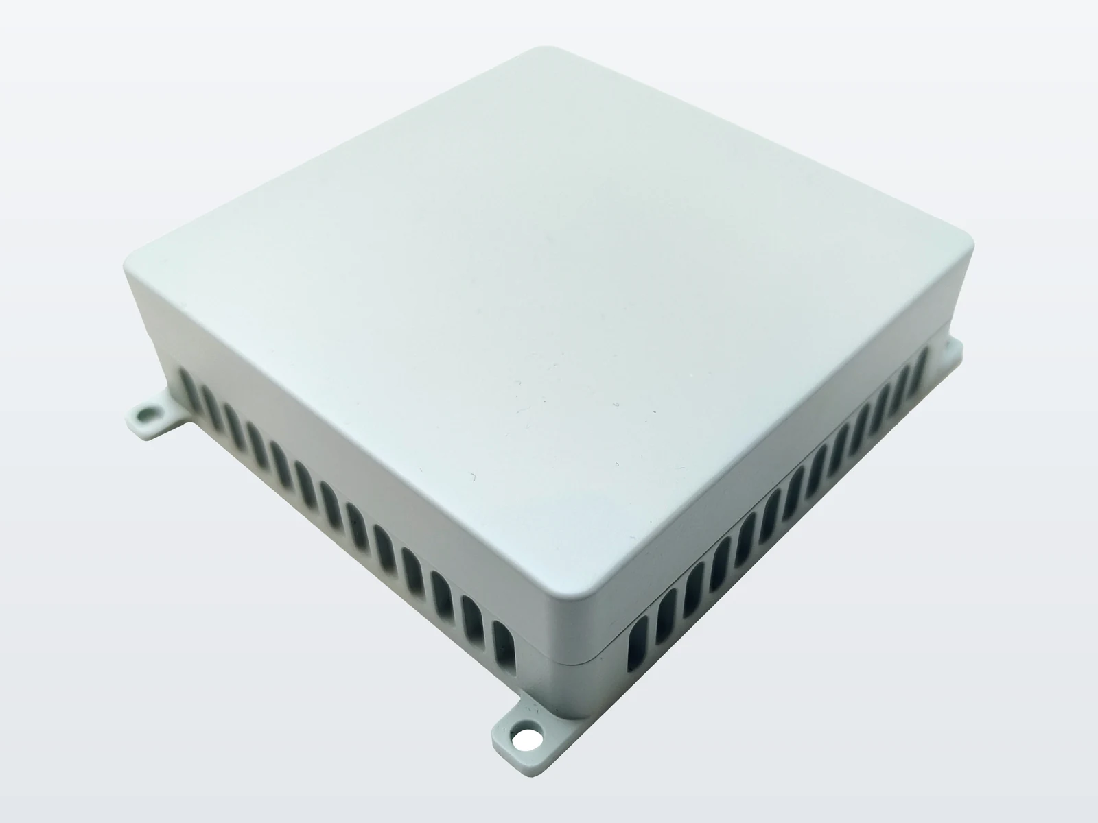 ResiNavAnti-Jamming TerminalsProduct image unavailable
Anti-Jamming Terminals
Compact 4-Element GNSS Anti-Jamming Terminal
A GNSS anti-jamming terminal designed for receiver and platform integration. Its documented signal configuration is available for engineering evaluation.
Documentation: Public datasheet available
PRODUCT OVERVIEW
This anti-jamming terminal provides the antenna-array reception and terminal functions needed between GNSS signals and the receiving navigation system. It is intended for engineering teams comparing terminal configurations for vehicles, marine equipment, industrial systems or custom navigation electronics. Selection should be based on the required signal configuration, receiver architecture, available installation space and the mechanical and electrical constraints of the target platform.
A documented constellation combination supports configuration matching during system selection.
The verified product record supports evaluation across more than one documented frequency band.
A verified channel configuration is available for receiver and system architecture review.
A verified antenna-element configuration provides a clear basis for comparing models in the series.
COMPACT PRODUCT SELECTION
Shortlist RN-S65-4CH-SNB when a small product envelope is a hard constraint and the required published signals are GPS L1 and BDS B1. Its documented dimensions are 65 × 65 × 21 mm, weight is no more than 130 g, and power consumption is no more than 6 W at normal temperature. These values make it a specific compact candidate to investigate, rather than simply another four-element entry in a catalogue.
The 6 W value is a consumption specification under the stated temperature condition, not an input-voltage rating or a complete platform power budget. The weight and dimensions describe the published product, not a verified installed assembly including brackets and cabling. The full dynamic specification panel below retains the other published parameters.
| Buying priority | Published candidate to review | What changes the choice |
|---|---|---|
| A compact GPS L1 / BDS B1 terminal with a 65 mm square product envelope. | RN-S65-4CH-SNB: 4 elements, 4 channels; 65 × 65 × 21 mm. Published RF output power: −75 to −85 dBm; impedance: 50 Ω. | Keep this candidate if its stated signal set and physical envelope meet the first screen. Receiver-specific RF fit and the installed clearance remain separate checks. |
| A record that explicitly includes GLONASS G1 alongside GPS L1 and BDS B1. | RN-009Pro-8CH-G1-WG-DT: 4 elements, 8 channels; 150 × 130 × 21 mm. Published RF output power: −70 to −60 dBm; impedance: 50 Ω. | The published signal record gives a reason to compare this larger footprint. It does not establish that an unlisted RN-S65 signal is unsupported or that eight channels perform better. |
| A separately identified anti-jamming and anti-spoofing product version. | RN2501-AJS-4CH-DPA: BDS B1 / GPS L1; 4 elements, 4 channels; 150 × 130 × 22 mm. | Compare its documented product scope rather than treating the same element and channel counts as interchangeability. Its larger product envelope requires a different space check. |
RF output power is another published difference, not just a smaller enclosure. RN-S65 lists −75 to −85 dBm; the G1 variant lists −70 to −60 dBm. Both state 50 Ω. These are the datasheets’ RF output-power entries, not antenna gain or an anti-jamming performance ranking.
For a hypothetical purchase requirement that explicitly calls for a terminal RF output of −70 to −60 dBm, the G1 record meets that numerical screen; RN-S65’s record does not. A need for the smaller RN-S65 envelope does not make the two published output ranges interchangeable. This comparison is not receiver-compatibility approval: the receiver’s input limits and the complete RF path remain separate checks. The source values are in the RN-S65 English datasheet and G1 English datasheet. Use the complete product catalogue when the required signal set or product role differs from these three records.
For an illustrative 80 × 80 mm space allocation, the RN-S65’s published 65 × 65 mm plan dimensions pass a product-body screen; the two 150 × 130 mm alternatives above do not. That does not approve the RN-S65 installation: connectors, cable bends, mounting hardware and access may require additional space. This example compares stated dimensions only; it is not a mechanical drawing or a mounting recommendation.
Do not select by height alone. RN-S65 and the G1 variant both list 21 mm, but their plan dimensions differ. If the small plan area is essential, retain RN-S65 as the compact candidate while resolving its installation envelope. If a specifically documented additional signal is essential, decide whether the larger candidate can be accommodated instead of assuming it is a drop-in replacement.
Distinguish the terminal from the installation parts in the enquiry. Ask whether the offered configuration includes the required mating connectors, cables and mounting items, or whether these are separately specified. The public RN-S65 datasheet does not identify a complete supplied installation kit, connector pinout or input-voltage range. Those items are unconfirmed—not promises of inclusion and not evidence of non-support.
Download the public English RN-S65 datasheet (PDF, Rev. 0.1) for the published record. Mechanical drawings, interface details and applicable test records are separate requests whose availability must be confirmed. For receiver input and bias questions, use the receiver compatibility guide; the datasheet review guide explains how to keep a missing specification distinct from a negative specification.
Use RFQ preparation below to send the chosen model, the limiting space or signal requirement and the required supply scope. The next decision is whether this compact documented configuration remains on the shortlist—not whether every four-element terminal can replace it.
INTEGRATION & INSTALLATION
Detailed mounting, interface and integration information is available during technical evaluation.
VERIFIED SPECIFICATIONS
All verified parameters are grouped in one continuous product datasheet for engineering review.
APPLICATION SCENARIOS
These are application contexts, not customer installations or completed projects.

Navigation equipment integration within commercial vehicles and autonomous system architectures.
View application
Navigation equipment selection for commercial vessels, survey platforms and marine electronics.
View application
Receiver and navigation integration within automation, robotic and industrial control equipment.
View application
Configuration review for purpose-built navigation electronics and platform-specific constraints.
View applicationREQUEST A QUOTE
Sharing these details helps engineering review the documented configuration against the intended integration.
DOCUMENTATION
Download the public English RN-S65 datasheet (PDF, Rev. 0.1). Ask separately whether mechanical drawings, connector/interface details and applicable test records can be supplied for the proposed configuration.
PRODUCT FAQ
The verified product record lists GPS L1 and BDS B1. Confirm the required signal configuration and receiver compatibility during engineering review.
The verified record lists 4 antenna elements and 4 channels for this configuration.
The verified record lists dimensions of 65 × 65 × 21 mm, weight of no more than 130 g, and power consumption of no more than 6 W at normal temperature.
ResiNav can review receiver compatibility, required bands and constellations, installation constraints, interfaces, quantity and delivery schedule. The appropriate configuration remains subject to engineering confirmation.
REQUEST A QUOTE
Use the product-specific RFQ to share receiver, installation and project requirements with the engineering team.