Multi-Constellation Configuration
A documented constellation combination supports configuration matching during system selection.
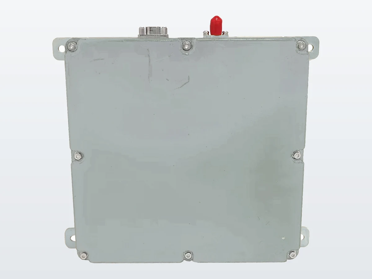 ResiNavAnti-Jamming TerminalsProduct image unavailable
Anti-Jamming Terminals
8-Element Multi-Constellation GNSS Anti-Jamming Terminal
A GNSS anti-jamming terminal designed for receiver and platform integration. Its documented signal configuration is available for engineering evaluation.
Documentation: Public datasheet available
PRODUCT OVERVIEW
This anti-jamming terminal provides the antenna-array reception and terminal functions needed between GNSS signals and the receiving navigation system. It is intended for engineering teams comparing terminal configurations for vehicles, marine equipment, industrial systems or custom navigation electronics. Selection should be based on the required signal configuration, receiver architecture, available installation space and the mechanical and electrical constraints of the target platform.
A documented constellation combination supports configuration matching during system selection.
The verified product record supports evaluation across more than one documented frequency band.
A verified antenna-element configuration provides a clear basis for comparing models in the series.
ENGINEERING OVERVIEW
RN-8AT-FULL-KGR-34V is an 8-element GNSS anti-jamming terminal in the Anti-Jamming Terminals family. Its verified record lists GPS and GLONASS, with GPS L1 and GLONASS G1, for receiver and platform integration in the published application contexts. The published mechanical and electrical record lists dimensions of 150 × 150 × 22.5 mm, weight of no more than 720 g, power consumption of no more than 19 W at normal temperature, and RF output frequencies of 1575.42 MHz and 1602 MHz. Evaluate it against those documented values. The formal model is retained, but no broader frequency coverage is inferred beyond the published record. Receiver channel count, interfaces, connectors, installation method and environmental ratings require engineering confirmation.
RN-8AT SIGNAL SCREEN
RN-8AT-FULL-KGR-34V has a useful, narrow first-pass role: its public record names GPS L1 and GLONASS G1, eight antenna elements, a 150 × 150 × 22.5 mm body and power consumption of no more than 19 W at normal temperature. Use those facts to decide whether to request a model-specific review. They do not establish the number of independent channels, a particular connector arrangement or compatibility with a named receiver.
The public RN-8AT English datasheet (Rev. 0.1) lists RF output frequencies of 1575.42 MHz and 1602 MHz, output power of −70 to −60 dBm and 50 Ω impedance. Those entries identify published RF characteristics, not a complete signal-to-port map. Do not turn “8-element” into “8-channel”: the reviewed product page and PDF do not state a channel count for this model.
| Current requirement | What is public | Appropriate decision |
|---|---|---|
| GPS L1 and GLONASS G1 are required | Both are explicitly listed for RN-8AT. | Keep the model for a receiver-specific review. Confirm how the two listed RF output frequencies are presented to the intended receiver before approving a design. |
| Another band or constellation is mandatory | The reviewed RN-8AT record names GPS L1 and GLONASS G1; it does not publish broader coverage. | Ask for the exact configuration. Missing public information does not establish support or lack of support. If the required signal is confirmed unavailable, compare another documented product. |
| A channel count is an approval criterion | No independent channel count is stated in the reviewed RN-8AT page or PDF. | Request an explicit channel definition for the proposed build. Do not infer it from eight antenna elements or from another model's naming. |
| The terminal must fit the available envelope | 150 × 150 × 22.5 mm, ≤720 g and ≤19 W at normal temperature are published. | Use these values for an initial space, mass and power screen; request the drawing, input-voltage range, mounting and connector details for release of the installation design. |
The RN-009Pro-8CH-G1-WG-DT page publishes a different 4-element, 8-channel record, while the RN2511 page publishes GPS L1, Galileo E1 and BDS B1. These are useful comparison paths if your required signal set differs. Neither model's channel count, dimensions or published anti-jamming figure can be transferred to RN-8AT. Compare each model's own product record and document revision.
Next step: if GPS L1 and GLONASS G1 match the first screen, request an RN-8AT configuration review with the receiver input, required channels if applicable, installation drawing and the exact open signal or interface question. Use the public PDF now; ask separately whether a mechanical drawing and interface record can be supplied for the proposed build.
INTEGRATION & INSTALLATION
Detailed mounting, interface and integration information is available during technical evaluation.
VERIFIED SPECIFICATIONS
All verified parameters are grouped in one continuous product datasheet for engineering review.
APPLICATION SCENARIOS
These are application contexts, not customer installations or completed projects.

Navigation equipment integration within commercial vehicles and autonomous system architectures.
View application
Navigation equipment selection for commercial vessels, survey platforms and marine electronics.
View application
Receiver and navigation integration within automation, robotic and industrial control equipment.
View application
Configuration review for purpose-built navigation electronics and platform-specific constraints.
View applicationREQUEST A QUOTE
Sharing these details helps engineering review the documented configuration against the intended integration.
DOCUMENTATION
Download the public English RN-8AT datasheet (Rev. 0.1, PDF). For a mechanical drawing, connector details, input-voltage range and signal-to-port mapping, ask what can be supplied for the proposed configuration.
PRODUCT FAQS
The verified product record lists GPS and GLONASS, with GPS L1 and GLONASS G1 frequency bands. The documented configuration has 8 antenna elements.
The verified record lists at least 110 dBc with 1 interferer, at least 100 dBc with 3 interferers and at least 90 dBc with 7 interferers. Documented interference types include narrowband high-power, wideband spectrum-matched, pulse, swept-frequency and mixed interference.
The verified record lists dimensions of 150 × 150 × 22.5 mm, weight of no more than 720 g and power consumption of no more than 19 W at normal temperature. RF output is documented at 1575.42 MHz and 1602 MHz, with power from −70 to −60 dBm and 50 Ω impedance.
Confirm receiver architecture, required constellations and bands, installation space, mounting arrangement, power requirements, cable routing, connector constraints and environmental requirements during engineering review.
REQUEST A QUOTE
Use the product-specific RFQ to share receiver, installation and project requirements with the engineering team.